3.3 A-2 STAGE ENGINE
For the same reasons as with the A-1 stage, a four-engine cluster has been chosen, having a total vacuum thrust of 600000 pounds ( 150000 pounds per engine). Because of the substantial vehicle performance gains obtainable through the use of high-energy propellants in upper booster stages, liquid oxygen ( ) and liquid hydrogen have been selected as propellants. For decades this combination has attracted the attention of rocket experimenters and developers. However, only relatively recently has the art of hydrogen engines reached maturity. Several major systems are in active development or in early flight application.
Through the years, the production and handling of the cryogenic propellant liquid oxygen ( or "LOX") has become a routine matter; its price has come down considerably. It can be reasonably expected that in the near future this will be equally true for liquid hydrogen. Both elements are abundantly available. Their combustion product-water vapor-is the most harmless of all propellant combinations, solid or liquid. Telemetry engineers like it because of the low attenuation effects of the exhaust gases on RF signals. an important aspect for vehicle guidance and telemetry. Most important, the yield in specific impulse of this combination is close to the theoretical maximum for chemical reactions. Only certain fluorine/hydrogen combinations are slightly higher (approximately 4 percent). However, the extreme toxicity of fluorine and fluorine compounds, both as a liquid and as components of combustion products, makes fluorine less attractive for operational use. By building the A-1 and A-2 stage a little larger, the same payload can be obtained as with fluorine. However, all advantages of liquid oxygen and hydrogen are retained, including the great amount of available experience.
Hydrogen does have its drawbacks. The principal one is low density, resulting in rather bulky tanks. For a typical oxygen-tohydrogen mixture ratio of , the corresponding volume ratio is inversed: . This disadvantage, however, is successfully offset for upper stages by the high energy yield ( ). It can be expected that the improved state of the art of ultralightweight vehicle and tank constructions will further increase the superiority of hydrogen systems for upper stages.
A secondary effect of low density is a high boiloff rate, unless tanks and lines are properly insulated. Because of the low density, and of the resulting large surface area of the containers, the heat input per unit hydrogen mass is high. Furthermore, the temperature of liquid hydrogen is sufficiently low to liquefy air on the tank surfaces. This sharply increases heat transfer rates, resulting in extreme boiloff rates. Tank and line insulation, therefore, is vital. Although techniques of rocket vehicle insulation are highly developed, some weight penalties are incurred.
Overall, however, a substantial net performance gain can be obtained for upper stages.
General Engine System Description
The A-2 engine is a single-start, fixed-thrust,
Table 3-3.-150K A-2 Stage Engine Operating Parameters [Vacuum conditions] Engine (turbopump feed): Thrust lb ..... 150000 Nominal single-firing duration sec. ..... 250 Specific impulse sec. ..... 434 Cxidizer : Flow rate ..... 288 Density. ..... 71.38 Fuel : Flow rate ..... 57.6 Density. ..... 4.42 Mixture ratio O/F ..... 5 Thrust chamber (tubular wall construction regeneratively cooled by fuel. Nozzle extension film cooled by turbine exhaust gas): Thrust lb ..... 149500 Specific impulse sec. ..... 440 Injector end pressure psia ..... 875 Nozzle stagnation pressure psia ..... 800 Oxidizer flow rate ..... 285.2 Fuel flow rate lb/sec ..... 54.5 Mixture ratio O/F ..... 5.22 efficiency Percent ..... 97.5 c* ft/sec ..... 7480 efficiency Percent ..... 101 ..... 1.895 Contraction ratio ..... 1.60 Expansion ratio ..... 40 Throat area, . in ..... 98.6 L* ..... in ..... 26 Nozzle contour ..... 75 percent bell Oxidizer side: Injector pressure drop psi ..... 160 Torus dome pressure drop. psi ..... 40 Line pressure drop psi ..... 20 Main valve pressure drop psi ..... 20 Calibration orifice pressure drop psi ..... 60 Pump inlet pressure psia ..... 35 Pump discharge pressure psia ..... 1175 Developed pump head ft ..... 2305 Pump weight flow rate. lb/sec ..... 290.5 Pump volumetric flow rate gpm ..... 1830 Heat exchanger bleed (oxidizer tank pressurization) lb/sec ..... 2.5 Pump: Shaft power bhp. ..... 1910 Efficiency Percent ..... 64 Shaft speed rpm. ..... 8600 Turbine: Inlet pressure psia ..... 700 Inlet temperature. ..... 1200 Pressure ratio ..... 16 Gas flow rate ..... 1.58 Shaft power bhp. ..... 1940 Efficiency Percent ..... 54.3 Shaft speed rpm. ..... 8600 Shaft torque in-lb ..... 14200 Fuel side: Injector pressure drop psi ..... 100 Jacket and manifold pressure drop psi ..... 325 Line pressure drop. psi ..... 20 Main valve pressure drop psi ..... 20 Calibration orifice pressure drop psi ..... 60 Pump inlet pressure psia ..... 25 Pump discharge pressure psia ..... 1400 Developed pump head ..... 44800 ft Pump weight low rate ..... 59.8 lb/sec Pump volumetric now rate ..... 6080 gpm Heat exchanger bleed ..... 2.2 lb/sec Pump: Shaft power ..... 0 bhp. Efficiency ..... 80 Percent Shaft speed ..... 27000 Chamber coolant passage bleed for fuel tank pressurization lb/sec ..... 2.2 Turbine: Inlet pressure psia ..... 700 Inlet temperature ..... 1200 Pressure ratio ..... 16 Gas flow rate ..... 4.32 lb/sec Shaft power ..... 6100 bhp. Efficiency ..... 62.5 Shaft speed ..... 27000 rpm. Shaft torque ..... 14250 Tapoff gas from thrust chamber for turbine drive: Pressure ..... 750 Temperature ..... 1200 Weight flow rate lb/sec ..... 5.9 Mixture ratio O/F ..... 0.90 Thrust vector control: Minimum acceleration rad/sec ..... 2 Maximum velocity deg/sec. ..... 15 Displacement deg. ..... gimbaled, bipropellant system. The thrust chamber features a combination of fuel regenerative cooling, and film cooling with turbine exhaust gas. The chamber assembly is fed by two independent, direct-drive centrifugal turbopumps. For the fuel, an alternative axial pump may be chosen. Each operates at optimum speed. Hot gases are tapped off from the main combustion chamber to power the turbines. A hot gas orifice in the tapoff duct controls the engine thrust level. The turbines are gas coupled in parallel. Their exhaust gases are routed to the thrust chamber and injected in the expansion area ratio plane. Thus the gases provide film cooling for the nozzle portion from there to the area ratio plane. The remainder of the chamber, above the plane, is regeneratively cooled ( pass). Helium gas is used to actuate the controls. No lubricants or any other fluids are used which could freeze at low temperatures. The engine is started by the hot gases generated by a solid-grain turbine spinner. Chlorine trifluoride , which is hypergolic with , is used to ignite the combustion chamber. Both turbine spinner and igniter fluid are insulated and electrically temperature conditioned from a ground source until first-stage takeoff. Gaseous hydrogen is bled from the thrust chamber coolant passage to pressurize the vehicle muin fuel tank. A small portion of liquid oxvgen bled from the oxidizer pump discharge is heated in a heat exchanger and used for vehicle main oxidizer tank pressurization.
A listing of the A-2 engine operating parameters is presented in table 3-3. The engine schematic diagram is shown in figure 3-3. Note that engine parameters are based on vacuum conditions. This is justified and customary, if a stage starts and performs in vacuum for its entire duration. In the case of the A-2 stage, the starting altitude of 250000 feet is not an absolute vacuum, but for all practical purposes may be considered absolute.
Thrust-vector control is achieved by gimbaling the entire engine. It weighs apploximately 2181 pounds dry, 2317 pounds wet, and 2292 pounds at burnout. The overall dimensions and the preliminary design layout of the A-2 engine are shown in figure 3-4.
System Operation
The starting method of the A-2 engine (figs. 3-3 and ) is a "turbine spin start," for very fast buildup (less than 2 seconds from start signal to main stage). Starting power is furnished
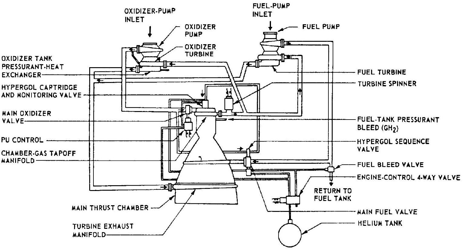 Figure 3-3.-A-2 stage engine system schematic diagram.
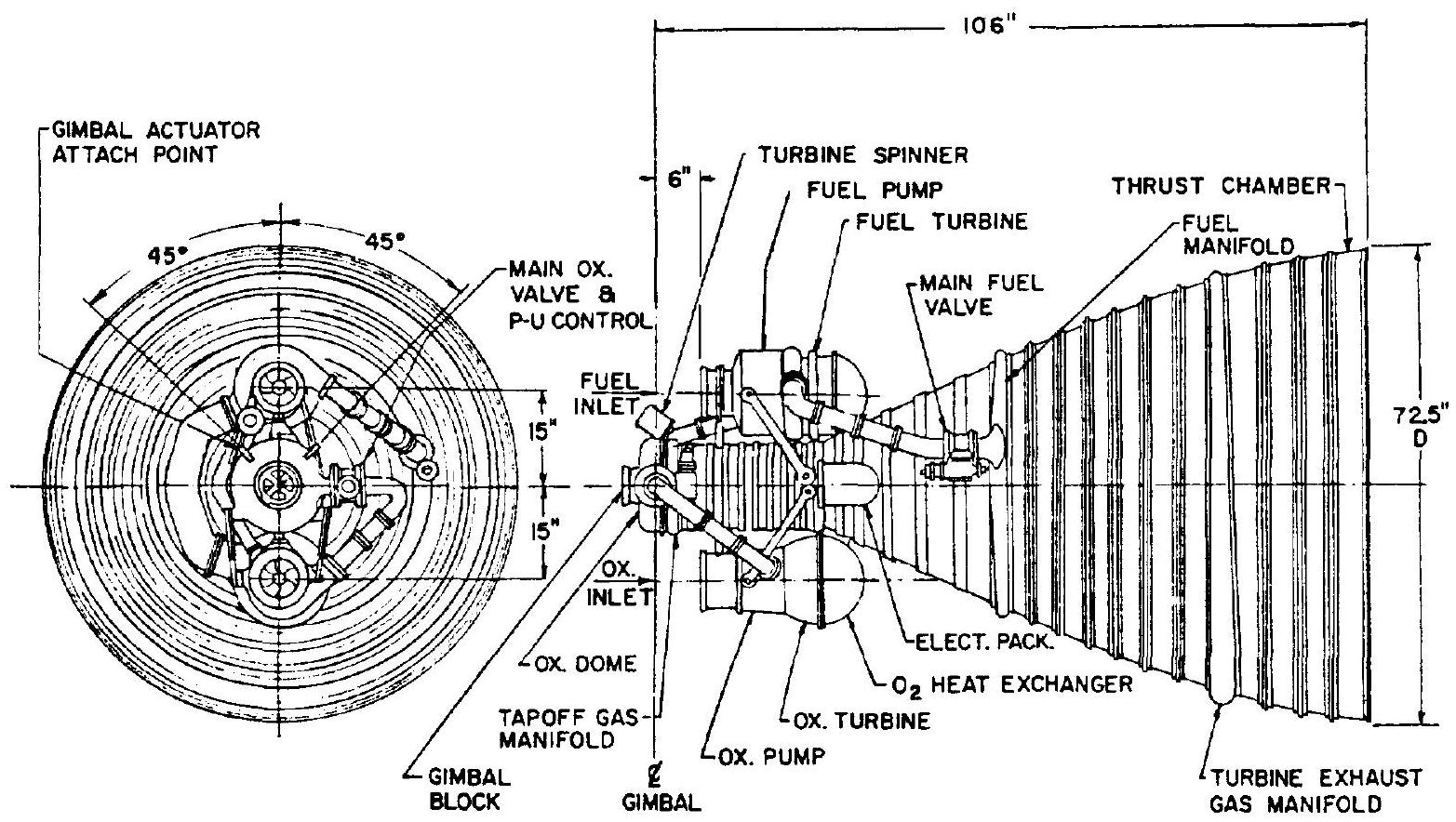 Figure 3-4.-150K A-2 stage engine system preliminary layout.
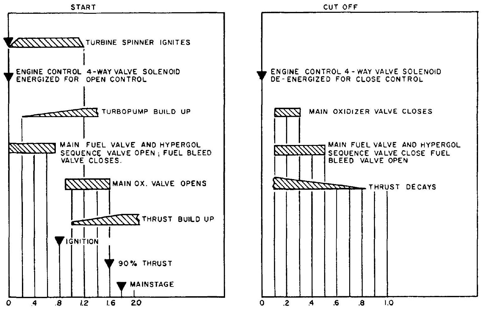 Figure 3-5.-A-2 engine system sequence diagram.
by a turbine spinner. Chamber tapoff gases then bootstrap the turbine and main stage operational level is established.
Starting Sequence
As part of the separation and staging sequence, a vehicle programer furnishes a start signal to the engine, which ignites the turbine spinner and supplies hot gases at to turbines and combustion chamber. This signal also energizes the solenoid of the engine control valve, which vents the closing side of both main propellant valve actuators and pressurizes the opening side of the fuel valve actuator with helium gas. Simultaneously, the hypergol sequence valve, which is mechanically linked to the main fuel valve, is opened and the actuator of the normally open fuel bleed valve is pressurized to close. The fuel flows through the chamber cooling jacket under increasing pump discharge pressure and injects into the combustion chamber. Ignition is achieved by the hypergolic reaction between hydrogen and the slug of chlorine trifluoride forced into the chamber by increased oxidizer-pump discharge pressure.
When the main fuel valve reaches the 90 percent open position, ports integral with the actuating piston open and permit helium gas to flow through the hypergol monitor valve and to pressurize the open side of the main oxidizer valve actuator. The main oxidizer valve opens, admitting oxidizer to the chamber where pressure builds up rapidly. Chamber tapoff gases bootstrap the turbines to main stage operation. The spinner will burn for about 1.2 seconds. After the main stage is achieved, the propellantutilization servo system will begin to function.
Cutoff Sequence
The cutoff signal, received from the vehicle programer, deenergizes the engine control valve causing it to close. This vents the open side and pressurizes the closing side of the main propellant valve actuators. The main oxidizer valve is made to close faster than the main fuel valve, by proper orificing of the helium lines, to assure a fuel-rich cutoff. Engine thrust decays. The fuel bleed valve opens after the helium pressure in its actuator is vented.